Audi A4 diesel engines diagrams
Audi A4 engine diagram - Audi A4 diesel engines diagrams
Audi A4 4-cylinder diesel engines:
Engines of 1.9 l - with one camshaft (OHC). The Cam shaft located in a head of cylinders, is set in motion through a toothed belt from a bent shaft. Fuel injection is carried out by pumps-atomizers in which are united a high pressure fuel pump, the valve of steering and a spray jet. Pumps-atomizers are set in motion from a cam shaft through additional cams. The engine is equipped by a turbo-compressor with changeable geometry turbines (VTG-supercharger).
Audi A4 engine diagram - the diesel 4-cylinder engine of 1.9 l TDI

1 - a cam shaft; 2 - the block the pump-atomizer; 3 - a toothed belt; 4 - a candle; 5 - V belt; 6 - a bent shaft; 7 - the oil pump; 8 - an oil-level indicator; 9 - an oil filter; 10 - a flywheel; 11 - an oil refrigerator; 12 - a refrigerator of air of forced aspiration.
6-cylinder diesel engines:
Engines - V-shaped DOHC with two inlet and two outlet valves on the cylinder. Each number of cylinders has on two cam shafts. One toothed belt actuates a cam shaft of inlet valves which in turn through a toothed gearing rotates a cam shaft of outlet valves.
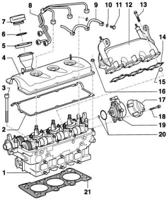
Audi A4 engine diagram - cylinder block head (it is shown left). The Diesel engine of 2.5 l

1 - the left head of cylinders; 2 - a sealing gasket of a cover of a head of cylinders; 3 - a bolt of fastening of a head of cylinders; 4 - a cover a head of cylinders; 5 - a ring; 6 - sealing; 7 - a cover; 8 - fuel pipe ducts; 9 - the returnable pipe duct; 10 - a ring gasket; 11 - a bolt; 12 - the inlet pipe duct; 13 - a bolt; 14 - a sealing gasket; 15 - the barrel; 16 - nuts; 17 - heat-shielding sheet; 18 - a bolt; 19 - the vacuum pump of the booster of a brake; 20 - a ring gasket of the vacuum pump; 21 - a sealing gasket of a head of cylinders.


